
問1
次の各文章の[1]~[13]の中に入れるべき最も適切な字句等をそれぞれの解答群から選び、その記号を答えよ。(配点計50点)
(2)三相回路
図1に示すように、対称三相交流電源に接続された負荷がある。
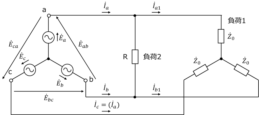
図1
ここで、電源の相電圧を\(\mathrm{\dot{E}_{a}}\)、\(\mathrm{\dot{E}_{b}}\)、\(\mathrm{\dot{E}_{c}}\)、線間電圧を\(\mathrm{\dot{E}_{ab}}\)、\(\mathrm{\dot{E}_{bc}}\)、\(\mathrm{\dot{E}_{ca}}\)、線電流を\(\mathrm{\dot{I}_{a}}\)、\(\mathrm{\dot{I}_{b}}\)、\(\mathrm{\dot{I}_{c}}\)とする。一方、負荷1はインピーダンス\(\mathrm{\dot{Z}_{0}}\)を結線した平衡三相負荷であり、a相線電流\(\mathrm{\dot{I}_{a1}}\)の位相は\(\mathrm{\dot{E}_{a}}\)に対してφ[rad]だけ遅れている。また、負荷2はa相とb相の間に接続された抵抗Rであり、この電流を\(\mathrm{\dot{I}_{a2}}\)とする。この回路において、有効電力及び無効電力を求める二つの方法を考える。ただし、負荷以外のインピー ダンスは無視するものとする。また、無効電力は遅れを正とする。
1)有効電力と無効電力 第一の方法
負荷1と負荷2が相互に影響しないことから、別々の負荷として考えて、その結果を合算する。
ⅰ)負荷1のみを考える。
三相交流の電源は対称で負荷は平衡であるので、線電流\(\mathrm{\dot{I}_{a1}}\)は次式のように表される。
\[\mathrm{\dot{I}_{a1}=\colorbox{cyan}{[ 5 ]}\tag{1}}\]
また、電圧\(\mathrm{\dot{E}_{a}}\)の大きさを\(\mathrm{E_{a}}\)、\(\mathrm{\dot{E}_{b}}\)の大きさを\(\mathrm{E_{b}}\)、\(\mathrm{\dot{E}_{c}}\)の大きさを\(\mathrm{E_{c}}\)、\(\mathrm{\dot{E}_{ab}}\)の大きさ\(\mathrm{E_{ab}}\)、電流\(\mathrm{\dot{I}_{a1}}\)の大きさを\(\mathrm{I_{a1}}\)、\(\mathrm{\dot{I}_{b1}}\)の大きさを\(\mathrm{I_{b1}}\)、\(\mathrm{\dot{I}_{c1}}\)の大きさを\(\mathrm{I_{c1}}\)とすると、\(\mathrm{E_{a}=E_{b}=E_{c}}\)、\(\mathrm{I_{a1}=I_{b1}=I_{c1}}\)であるので、負荷1の三相の有効電力\(\mathrm{P_{L1}}\)、無効電力\(\mathrm{Q_{L1}}\)は次式のように表される。
\[\mathrm{P_{L1}=\colorbox{cyan}{[ 6 ]}\tag{2}}\]
\[\mathrm{Q_{L1}=\colorbox{cyan}{[ 7 ]}\tag{3}}\]
(ア)\(\displaystyle\mathrm{\frac{\dot{E}_{a}}{\dot{Z}_{0}}}\)
(イ)\(\displaystyle\mathrm{\frac{\dot{E}_{ab}}{2\dot{Z}_{0}}}\)
(ウ)\(\displaystyle\mathrm{\frac{\dot{E}_{ab}}{\sqrt{3}\dot{Z}_{0}}}\)
(エ)\(\displaystyle\mathrm{3E_{a}I_{a1}cos\phi}\)
(オ)\(\displaystyle\mathrm{3E_{a}I_{a1}sin\phi}\)
(カ)\(\displaystyle\mathrm{3E_{ab}I_{a1}cos\phi}\)
(キ)\(\displaystyle\mathrm{3E_{ab}I_{a1}sin\phi}\)
(ク)\(\displaystyle\mathrm{\sqrt{3}E_{a}I_{a1}cos\phi}\)
(ケ)\(\displaystyle\mathrm{\sqrt{3}E_{a}I_{a1}sin\phi}\)
[5](ア)\(\displaystyle\mathrm{\frac{\dot{E}_{a}}{\dot{Z}_{0}}}\)
[6](エ)\(\displaystyle\mathrm{3E_{a}I_{a1}cos\phi}\)
[7](オ)\(\displaystyle\mathrm{3E_{a}I_{a1}sin\phi}\)
ⅱ)負荷2のみを考える。
a相とb相の間に抵抗Rが接続されるので、電流\(\mathrm{\dot{I}_{a2}}\)は次式のように表される。
\[\mathrm{\dot{I}_{a2}=\colorbox{cyan}{[ 8 ]}\tag{4}}\]
ⅲ)ⅰ)及びⅱ)をふまえ、三相全体を考える。
三相交流電源から見ると、抵抗Rで消費される有効電力が増加することになるので、三相の有効電力\(\mathrm{P_{3}}\)、無効電力\(\mathrm{Q_{3}}\)は次式のように表される。
\[\mathrm{P_{3}=\colorbox{cyan}{[ 9 ]}\tag{5}}\]
\[\mathrm{Q_{3}=Q_{L1}\tag{6}}\]
このとき、交流電源のa相線電流\(\mathrm{\dot{I}_{a}}\)は、\(\mathrm{\dot{I}_{a1}+\dot{I}_{a2}}\)となっている。
(ア)\(\displaystyle\mathrm{\frac{\dot{E}_{a}}{R}}\)
(イ)\(\displaystyle\mathrm{\frac{\dot{E}_{ab}}{R}}\)
(ウ)\(\displaystyle\mathrm{\frac{\dot{E}_{a}+\dot{E}_{b}}{R}}\)
(エ)\(\displaystyle\mathrm{P_{L1}+\frac{\dot{E}_{a}^{2}}{R}}\)
(オ)\(\displaystyle\mathrm{P_{L1}+\frac{3\dot{E}_{a}^{2}}{R}}\)
(カ)\(\displaystyle\mathrm{P_{L1}+\frac{4\dot{E}_{a}^{2}}{R}}\)
[8](イ)\(\displaystyle\mathrm{\frac{\dot{E}_{ab}}{R}}\)
[9](オ)\(\displaystyle\mathrm{P_{L1}+\frac{3\dot{E}_{a}^{2}}{R}}\)
2)有効電力と無効電力 第二の方法
負荷1と負荷2を合成した不平衡三相負荷として三相回路を考える。
ⅰ)負荷1と負荷2を合成する。
負荷1と負荷2を合成したΔ結線不平衡三相負荷回路は図2のように示される。
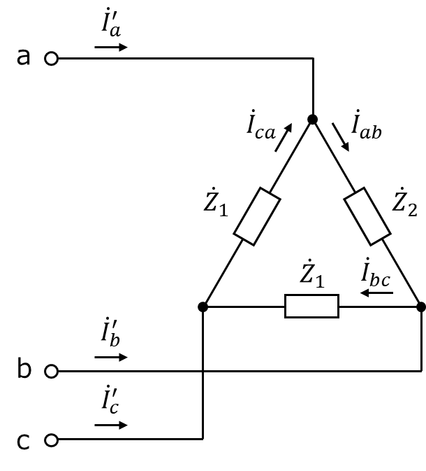
図2
ここで、線電流を\(\mathrm{\dot{I}_{a}’}\)、\(\mathrm{\dot{I}_{b}’}\)及び\(\mathrm{\dot{I}_{c}’}\)とする。この回路において、b相とc相の間の負荷及びc相とa相の間のインピーダンス\(\mathrm{\dot{Z}_{1}}\), a相とb相の間のインピーダンス\(\mathrm{\dot{Z}_{2}}\)は、それぞれ次式のように表される。
\[\mathrm{\dot{Z}_{1}=\colorbox{cyan}{[ 10 ]}\tag{7}}\]
\[\mathrm{\dot{Z}_{2}=\colorbox{cyan}{[ 11 ]}\tag{8}}\]
(ア)\(\displaystyle\mathrm{3\dot{Z}_{0}}\)
(イ)\(\displaystyle\mathrm{\frac{1}{3}\dot{Z}_{0}}\)
(ウ)\(\displaystyle\mathrm{\frac{1}{\sqrt{3}}\dot{Z}_{0}}\)
(エ)\(\displaystyle\mathrm{\dot{Z}_{1}+R}\)
(オ)\(\displaystyle\mathrm{\frac{\dot{Z}_{0}R}{\dot{Z}_{0}+R}}\)
(カ)\(\displaystyle\mathrm{\frac{\dot{Z}_{1}R}{\dot{Z}_{1}+R}}\)
[10](ア)\(\displaystyle\mathrm{3\dot{Z}_{0}}\)
[11](カ)\(\displaystyle\mathrm{\frac{\dot{Z}_{1}R}{\dot{Z}_{1}+R}}\)
ⅱ)不平衡三相負荷に流れ込む線電流を求めることで、有効電力及び無効電力が分かる。
図2に示すように、a相とb相の間のインピーダンス\(\mathrm{\dot{Z}_{2}}\)に流れる電流を\(\mathrm{\dot{I}_{ab}}\)、c相とa相の間のインピーダンス\(\mathrm{\dot{Z}_{1}}\)に流れる電流を\(\mathrm{\dot{I}_{ca}}\)とすると、a相線電流\(\mathrm{\dot{I}_{a}’}\)は次式のように表される。
\[\mathrm{\dot{I}_{a}’=\dot{I}_{ab}-\dot{I}_{ca}=\colorbox{cyan}{[ 12 ]}\tag{9}}\]
対称三相の線間電圧と相電圧の関係式として、次式のようになる。
\[\mathrm{\dot{E}_{ab}-\dot{E}_{ca}=\colorbox{cyan}{[ 13 ]}\tag{10}}\]
式(7)、式(8)及び式(10)の結果を使って式(9)を計算し、式(1)と式(4)の結果を代入すると、\(\mathrm{\dot{I}_{a}’}\)は次式のように表され、\(\mathrm{\dot{I}_{a}’=\dot{I}_{a}}\)であることが示される。
\[\mathrm{\dot{I}_{a}’=\dot{I}_{a1}+\dot{I}_{a2}\tag{11}}\]
同様の手順で\(\mathrm{\dot{I}_{b}’=\dot{I}_{b}}\)、\(\mathrm{\dot{I}_{c}’=\dot{I}_{c}}\)となるので、有効電力及び無効電力については、第一の方法と同じ結果となることが分かる。
(ア)\(\displaystyle\mathrm{\dot{E}_{a}}\)
(イ)\(\displaystyle\mathrm{2\dot{E}_{a}}\)
(ウ)\(\displaystyle\mathrm{3\dot{E}_{a}}\)
(エ)\(\displaystyle\mathrm{\frac{\dot{E}_{ab}}{\dot{Z}_{2}}+\frac{\dot{E}_{ca}}{\dot{Z}_{1}}}\)
(オ)\(\displaystyle\mathrm{\frac{\dot{E}_{ab}}{\dot{Z}_{2}}-\frac{\dot{E}_{ca}}{\dot{Z}_{1}}}\)
(カ)\(\displaystyle\mathrm{-\frac{\dot{E}_{ab}}{\dot{Z}_{2}}+\frac{\dot{E}_{ca}}{\dot{Z}_{1}}}\)
[12](オ)\(\displaystyle\mathrm{\frac{\dot{E}_{ab}}{\dot{Z}_{2}}-\frac{\dot{E}_{ca}}{\dot{Z}_{1}}}\)
[13](ウ)\(\displaystyle\mathrm{3\dot{E}_{a}}\)
解説
[5]線電流\(\mathrm{\dot{I}_{a1}}\)
線電流\(\mathrm{\dot{I}_{a1}}\)は負荷\(\mathrm{\dot{Z}_{0}}\)に流れる電流である。負荷\(\mathrm{\dot{Z}_{0}}\)に印加される電圧は、平衡三相負荷より\(\mathrm{\dot{E}_{a}}\)となる。よって、線電流\(\mathrm{\dot{I}_{a1}}\)は、次式で表される。
\[\mathrm{\dot{I}_{a1}=\frac{\dot{E}_{a}}{\dot{Z}_{0}}}\]
[6]有効電力\(\mathrm{P_{L1}}\)
三相回路の有効電力\(\mathrm{P_{L1}}\)は、1相の電力を3倍すれば良いので、次式で表される。
\[\mathrm{P_{L1}=3E_{a}I_{a1}\cos\varphi}\]
[7]無効電力\(\mathrm{Q_{L1}}\)
無効電力\(\mathrm{Q_{L1}}\)も同様に、次式であわわされる。
\[\mathrm{Q_{L1}=3E_{a}I_{a1}\sin\varphi}\]
無効電力の場合は、\(\mathrm{\sin\varphi}\)を掛ける事に注意して下さい。
[8]負荷2に流れる電流\(\mathrm{\dot{I}_{a2}}\)
負荷2へ印加される電圧は、\(\mathrm{\dot{E}_{ab}}\)であるから、負荷2に流れる電流\(\mathrm{\dot{I}_{a2}}\)は次式で表される。
\[\mathrm{\dot{I}_{a2}=\frac{\dot{E}_{ab}}{R}}\]
[9]全有効電力\(\mathrm{P_{3}}\)
全有効電力\(\mathrm{P_{3}}\)は、負荷1の有効電力\(\mathrm{P_{L1}}\)と負荷2の有効電力\(\mathrm{P_{L2}}\)の和である。負荷2の有効電力\(\mathrm{P_{L2}}\)は、[8]の負荷電流\(\mathrm{\dot{I}_{a2}}\)より、次式で表される。
\[\mathrm{P_{L2}=E_{ab}I_{a2}=\frac{E_{ab}^2}{R}}\]
\(\mathrm{E_{ab}=\sqrt{3}E_{a}}\)であるから、
\[\mathrm{P_{L2}=\frac{(\sqrt{3}E_{a})^2}{R}=\frac{3E_{a}^2}{R}}\]
よって、全有効電力\(\mathrm{P_{3}}\)は、次式で表される。
\[\mathrm{P_{3}=P_{L1}+P_{L2}=P_{L1}+\frac{3E_{a}^2}{R}}\]
[10]インピーダンス\(\dot{Z}_{1}\)
インピーダンス\(\dot{Z}_{1}\)は、インピーダンス\(\dot{Z}_{0}\)のスターデルタ変換後である。
三相平衡回路におけるスター(Y)のインピーダンス\(\dot{Z}_{Y}\)とデルタ(△)のインピーダンス\(\dot{Z}_{\triangle}\)には次式の関係がある。
\[\mathrm{\dot{Z}_{\triangle}=3\dot{Z}_{Y}}\]
よって、インピーダンス\(\dot{Z}_{1}\)は、次式で表される。
\[\mathrm{\dot{Z}_{1}=3\dot{Z}_{0}}\]
[11]インピーダンス\(\dot{Z}_{2}\)
インピーダンス\(\dot{Z}_{2}\)は、\(\dot{Z}_{2}\)と負荷2のインピーダンスRの並列和であるから、次式で表される。
\[\mathrm{\dot{Z}_{2}=\frac{\dot{Z}_{1}R}{\dot{Z}_{1}+R}}\]
[12]a相線電流\(\mathrm{\dot{I}’_{a1}}\)
[10]及び[11]で求めたインピーダンス\(\dot{Z}_{1}\)、\(\dot{Z}_{2}\)を用いて計算します。
\[\mathrm{\dot{I}_{a}’=\dot{I}_{ab}-\dot{I}_{ca}=\frac{\dot{E}_{ab}}{\dot{Z}_{2}}-\frac{\dot{E}_{ca}}{\dot{Z}_{1}}}\]
[13]線間電圧の差分\(\mathrm{\dot{E}_{ab}-\dot{E}_{ca}}\)
\[\mathrm{\dot{E}_{ab}-\dot{E}_{ca}=(\dot{E}_{a}-\dot{E}_{b})-(\dot{E}_{c}-\dot{E}_{a})}\]
\[\mathrm{=2\dot{E}_{a}-\dot{E}_{b}-\dot{E}_{c}}\]
ベクトル図より、\(\mathrm{\dot{E}_{b}+\dot{E}_{c}=-\dot{E}_{a}}\)である。よって、
\[\mathrm{\dot{E}_{ab}-\dot{E}_{ca}=3\dot{E}_{a}}\]
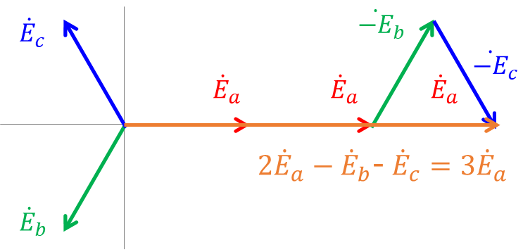
図3 線間電圧のベクトル


コメント